|
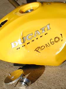
Meet Pongo!
Pongo! is my new Monster (as of 2002). Well, not really new, but new to me. Some guy said he's got a Monster for sale cheap on a mail list. I can't resist... and I'm in the van to the City of Angels on my latest adventure! I'm pretty excited about this salvaged and neglected bike, but couldn't come up with a name. Zina suggested Pongo. He's one of Troy Bayliss's mechanics. Definitely a name with character, so Pongo! he is! |
| Pongo came with some issues. I'll try to list them out. The tank was leaking fuel (because the locknut for the fuel level sending unit nut is cracked), right fork seal is leaking, sidestand is from a Honda (oh, the humanity), license plate rubs the tire, tail light is mounted on an angle, tires are shot, waaay dirty, battery acid has spilled about, and the bars are kinda screwed. Oh, and he had about 7 quarts of oil! I guess the sight glass was filled while on the Honda sidestand, which has extra added lean. The guy selling Pongo said he ran poorly. Well, that's certainly cause! |
 But wait, there's more!
I first took off the fuel tank to figure out what's going on with the fuel leak.
And it's the first step for changing the belts and adjusting the valves.
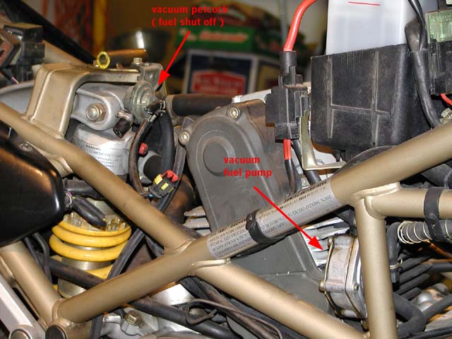
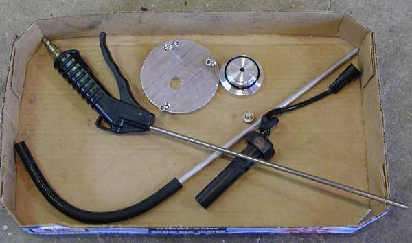
Carbureted Monsters have a reasonably complicated fuel system...
Fuel comes out of the tank and goes to a tank mounted fuel filter.
Then it flows to a vacuum operated fuel cutoff switch.
From there, it flows to a vacuum operated fuel pump and finally to the carbs.
The cutoff and pump are shown in the image... click on it for a full sized version.
But wait, there's more!
I first took off the fuel tank to figure out what's going on with the fuel leak.
And it's the first step for changing the belts and adjusting the valves.
Carbureted Monsters have a reasonably complicated fuel system...
Fuel comes out of the tank and goes to a tank mounted fuel filter.
Then it flows to a vacuum operated fuel cutoff switch.
From there, it flows to a vacuum operated fuel pump and finally to the carbs.
The cutoff and pump are shown in the image... click on it for a full sized version.
Well, as it turns out, the vacuum line running to the cutoff was split. This causes two conditions simultaneously: that the shut off wasn't fully opening AND there was a vacuum leak. |
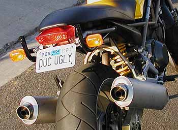
| I got to looking at pongo and noticed someone had already hacked off the stock frame tubes and then welded on a "cross bar" between them. Additionally, they welded on tabs for the turn signals. Then they bent up the eyelets for the tail section and kind of wedged the tail light up in there at an angle. Real ugly. Then they mounted the license plate on one of those japanese style bent sheet metal fender mounting brackets. It was sano enough except that it put the plate into the inner fender and tire on bumps. |
 For mounting the tail light, I used two pieces of 1 x .25 flat bar and machined a recess in it for the rubber
parts to fit to the lens. Then I drilled and tapped holes at the other end to mount to the bike.
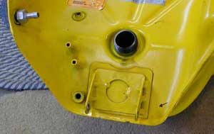
The "block" for holding the plate was a lot of fun.
I wanted to move the plate back a few inches to get away from the tire, but also have it angled.
I also wanted a "bomber" solution; one that wouldn't wiggle around at all.
So i dug through my bar stock and saw some 1 x 2 aluminum. I held the plate where i wanted it and then used my index finger as
a measuring stick. I cut the bar, made it parallel, then I got
out the digital level and set the block on the mill to 45 degrees and cut
the area to mount up one of my "license plate brackets". That's the black
anodized bar you see at the back of the billet block. Next I drilled and
tapped two M6 holes into the 45 degree plane before letting the part out of
the vice. Then, I drilled and tapped 2 M10 holes like 1.25 inches deep to mount the block to the frame.
Finally, I grabbed a 1/2" end mill and walked it all around the surface of the block to
make it look interesting. Click on the picture of Pongo's butt to see the "block" from underneath.
For mounting the tail light, I used two pieces of 1 x .25 flat bar and machined a recess in it for the rubber
parts to fit to the lens. Then I drilled and tapped holes at the other end to mount to the bike.
The "block" for holding the plate was a lot of fun.
I wanted to move the plate back a few inches to get away from the tire, but also have it angled.
I also wanted a "bomber" solution; one that wouldn't wiggle around at all.
So i dug through my bar stock and saw some 1 x 2 aluminum. I held the plate where i wanted it and then used my index finger as
a measuring stick. I cut the bar, made it parallel, then I got
out the digital level and set the block on the mill to 45 degrees and cut
the area to mount up one of my "license plate brackets". That's the black
anodized bar you see at the back of the billet block. Next I drilled and
tapped two M6 holes into the 45 degree plane before letting the part out of
the vice. Then, I drilled and tapped 2 M10 holes like 1.25 inches deep to mount the block to the frame.
Finally, I grabbed a 1/2" end mill and walked it all around the surface of the block to
make it look interesting. Click on the picture of Pongo's butt to see the "block" from underneath.
|
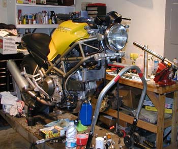 Pongo went up on the lift. To get to where you see Pongo now was a two step process.
First, I had him on a fork stand so I could change the front tire.
From previous experience on our RS250s, I thought I could just put the steering stem stand under there and away we go.
Well, I didn't notice that the forks had been dropped like an inch!
So it took more work than planned to make that happen!
Click on image for full size one. Note fork in vice in the background.
Pongo went up on the lift. To get to where you see Pongo now was a two step process.
First, I had him on a fork stand so I could change the front tire.
From previous experience on our RS250s, I thought I could just put the steering stem stand under there and away we go.
Well, I didn't notice that the forks had been dropped like an inch!
So it took more work than planned to make that happen!
Click on image for full size one. Note fork in vice in the background.
|
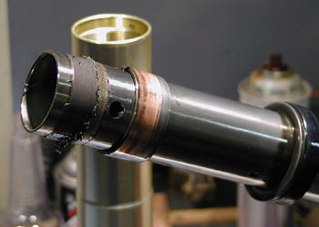
 With the fork lower clamped in the vice (with copper soft jaws) and with an oil pan under it, I first use an air impact to remove the bottom bolt.
Bottom bolts can sometimes be really stubborn and I learned long ago to hit `em with the stick right away.
Then you let most of the oil drain out in a controlled fashion.
The oil in Pongo's forks was crap.
Real nasty. The year old Redline in my Aprilia forks was drinkable in comparison.
Next, I clamp the upper several inches from the top in the vice (with rags) so I can remove the fork cap.
The cap was so stuck, I had to resort to using the air impact.
Ugh.
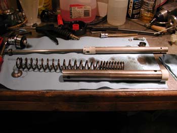
Now the fork guts are out.
That's the picture.
Click on it for large version.
On some forks, the springs bottom on the lower cartridge tube.
Not on these Showas.
Note the really really long spacer tube.
With the fork lower clamped in the vice (with copper soft jaws) and with an oil pan under it, I first use an air impact to remove the bottom bolt.
Bottom bolts can sometimes be really stubborn and I learned long ago to hit `em with the stick right away.
Then you let most of the oil drain out in a controlled fashion.
The oil in Pongo's forks was crap.
Real nasty. The year old Redline in my Aprilia forks was drinkable in comparison.
Next, I clamp the upper several inches from the top in the vice (with rags) so I can remove the fork cap.
The cap was so stuck, I had to resort to using the air impact.
Ugh.
Now the fork guts are out.
That's the picture.
Click on it for large version.
On some forks, the springs bottom on the lower cartridge tube.
Not on these Showas.
Note the really really long spacer tube.
|
 Now we hit a "luck of the draw" item in the rebuild.
In order to remove the oil seals, you have to slide hammer the outer tube off the inner tube.
The first step is to pry up the dust seal (the one you can see) then remove the wire clip that locks the oil seal into place.
Now you extend the forks all the way with force and hammer them apart.
The inner bushing is the foundation for all of this slide hammering...
the outer bushing comes to a stop resting against the inner bushing, which transfers the load to the big washer, which then pushes on the oil seal.
Note in the image how the outer bushing started overlapping the inner bushing!
They're now ruined.
Soooooo, when someone does your forks and the only parts they're quoting you are for the oil and/or dust seals... are they assuming that the bushings will be OK?
Sometimes they do survive the slide hammering without any sign of abuse.
As a general rule, I change the bushings whenever I slide hammer forks apart.
I have taken apart forks where it was apparent that a previous mechanic had turned the bushing around!
The bushings are what allows the forks to slide up and down smoothly.
Making them smaller is a bad thing.
The inner bushing is at the top of the inner fork tube (the shiney one) and rides along the inside of the top, outer tube.
The outer bushing is at the bottom of the outer tube "behind" or above the dust and oil seals.
This is the one that rides against the polished chrome of the lower, inner fork tube.
When you see wear in the chroming, it's probably from debris in the outer bushing.
Now we hit a "luck of the draw" item in the rebuild.
In order to remove the oil seals, you have to slide hammer the outer tube off the inner tube.
The first step is to pry up the dust seal (the one you can see) then remove the wire clip that locks the oil seal into place.
Now you extend the forks all the way with force and hammer them apart.
The inner bushing is the foundation for all of this slide hammering...
the outer bushing comes to a stop resting against the inner bushing, which transfers the load to the big washer, which then pushes on the oil seal.
Note in the image how the outer bushing started overlapping the inner bushing!
They're now ruined.
Soooooo, when someone does your forks and the only parts they're quoting you are for the oil and/or dust seals... are they assuming that the bushings will be OK?
Sometimes they do survive the slide hammering without any sign of abuse.
As a general rule, I change the bushings whenever I slide hammer forks apart.
I have taken apart forks where it was apparent that a previous mechanic had turned the bushing around!
The bushings are what allows the forks to slide up and down smoothly.
Making them smaller is a bad thing.
The inner bushing is at the top of the inner fork tube (the shiney one) and rides along the inside of the top, outer tube.
The outer bushing is at the bottom of the outer tube "behind" or above the dust and oil seals.
This is the one that rides against the polished chrome of the lower, inner fork tube.
When you see wear in the chroming, it's probably from debris in the outer bushing.
|
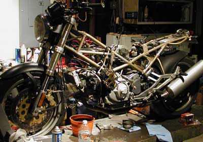 "Hi, my name is Chris Kelley. I own Ducatis..."
How many of you recognize a Ducati stripped down to its engine and frame?
How many have had this in their garage for days, weeks, or months at a time?
"Hi, my name is Chris Kelley. I own Ducatis..."
How many of you recognize a Ducati stripped down to its engine and frame?
How many have had this in their garage for days, weeks, or months at a time?
=) The forks are all done now, with yummy new seals and bushings. Oh, and "new" pads in the brakes. Oh yeah, the unbelievably "small" or high fork oil level specified in the Haynes manual agrees with the Ducati manual. I turned Pongo! around in the lift with his front wheel clamped in the vice. Now I'll be able to change the rear tire, chain, and sprockets. Today, I stripped off all the hardened fuel and vacuum lines and got to work with the valve adjustment. I think his closing shims have never ever been set. They ranged from .008" to .015" !!! The openers ranged from .004" to .006", so they weren't terribly off. He's got fresh, new belts, too. Next step is to sort out the fuel system, add oil, and hear Pongo roar! |
 I went to Napa and spent like $40 on all sorts of goofy little stuff that I needed for Pongo.
Fuses, hoses, clamps, odd ball junk.
To recap, the fuel system has 5 components: fuel tank, fuel filter, vacuum operated fuel shut off valve, vacuum operated fuel pump, and the carburetors.
Guess what?
They all use different sized fittings.
The tank has a spigot that's between 1/4" and 5/16".
The fuel pump has a 5/16" inlet and a 1/4" outlet, with a 5/16" vacuum line fitting.
The fuel shutoff valve has 1/4" inlet and outlet, with a 3/16" or 1/8" vacuum fitting.
Oh, and the carburetors have a 5/16" inlet.
I purchased a fuel filter with 5/16" fittings in and out.
And then I added component #6: a quick disconnect fitting with valves in each part, allowing the easy removal of the tank.
I've got a small cache of these in 1/4" and 5/16" so I was able to mix and match as desired.
I ended up moving the shut off so that it lives right next to the pump (in its stock location).
To do this, I used a wellnut in place of the rubber bushing and the fixed lug at the bottom of the fuel pump, then put the mount for the shutoff between the fuel pump and the frame.
Due to a lack of 5/16" hose, I had to use and/or make a couple of step up / step down fittings for the fuel system.
Also had to use them for the vacuum system, as both vacuum operated accessories had to be converted to the size of the fittings in the manifolds.
Then I went through the carbs real quick to unclog a few jets and found a Factory Jet Kit, too.
I went to Napa and spent like $40 on all sorts of goofy little stuff that I needed for Pongo.
Fuses, hoses, clamps, odd ball junk.
To recap, the fuel system has 5 components: fuel tank, fuel filter, vacuum operated fuel shut off valve, vacuum operated fuel pump, and the carburetors.
Guess what?
They all use different sized fittings.
The tank has a spigot that's between 1/4" and 5/16".
The fuel pump has a 5/16" inlet and a 1/4" outlet, with a 5/16" vacuum line fitting.
The fuel shutoff valve has 1/4" inlet and outlet, with a 3/16" or 1/8" vacuum fitting.
Oh, and the carburetors have a 5/16" inlet.
I purchased a fuel filter with 5/16" fittings in and out.
And then I added component #6: a quick disconnect fitting with valves in each part, allowing the easy removal of the tank.
I've got a small cache of these in 1/4" and 5/16" so I was able to mix and match as desired.
I ended up moving the shut off so that it lives right next to the pump (in its stock location).
To do this, I used a wellnut in place of the rubber bushing and the fixed lug at the bottom of the fuel pump, then put the mount for the shutoff between the fuel pump and the frame.
Due to a lack of 5/16" hose, I had to use and/or make a couple of step up / step down fittings for the fuel system.
Also had to use them for the vacuum system, as both vacuum operated accessories had to be converted to the size of the fittings in the manifolds.
Then I went through the carbs real quick to unclog a few jets and found a Factory Jet Kit, too.
After sorting out the fuel system, I added oil, put on the airbox, ignition components, and the battery. Wow! The moment is here! I open the garage door, put on my ear muffs, ignition switch to on, push the button. Nothing. Huh. Ear muffs off, push start button. Click. Release start button. Click. OK, bad solenoid. So I try jumping from the (+) lead to the starter itself, but there's just not enough current to overcome the strain on the starter when the choke or throttle is opened. =( Oh, and my new fuel sending unit was leaking. Turns out it didn't come with a new gasket. Ninety facking dollars and it doesn't come with a gasket?! I drained the tank (easy to do with quick disconnects!!) and added the gasket from my old sending unit. Will test later... |
OK, the "old" gasket for the fuel level sending unit worked.
I'm pretty pleased about that.
BUT... more pleasing is that my "generic" Yamaha starter solenoid came in.
I've got inquiries in with a couple manufacturers to get the proper units, though.
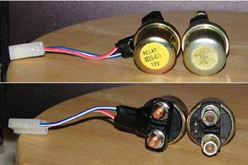 Other than the pigtail, this solenoid is absolutely identical to the OEM Ducati one, with the same manufacturer's mark on the back.
It came with a new "rubber", too.
The Yammie one has that pigtail on it instead of the leave-you-stranded-at-the-gas-station slip-fit job.
The connector has the blades perpendicular, instead of parallel.
I don't have perpendicular 2 conductor connectors in my stache, so I pulled the pins and put one of my connectors on it.
Then I cut the wiring harness on Pongo (even on a "junker" this makes me sigh) and installed the proper mate to the connector.
But I couldn't yet light off the ignition, as I had to finish putting on the airbox because the grounding strap is tied in with one of the mounts.
With that completed, I engaged the choke, powered the ignition, and held my breath as I thumbed the start button.
Pongo had the best possible start up: he simply "became running".
No catch, tumble, then run.
No.
Simply became running.
I was and am very happy for Pongo!
I left him on the choke for a goodly while to warm up thoroughly, then cut the choke and he settled into a nice idle.
I'm not even going to bother with the mercury sticks, as tickover is even and without lumps or hiccups.
Hmmm, what's that?
Oh, the charge light is on.
Tap the revs and the light goes out.
Haven't seen it since, but will allocate an RR51 for Pongo! soon.
Other than the pigtail, this solenoid is absolutely identical to the OEM Ducati one, with the same manufacturer's mark on the back.
It came with a new "rubber", too.
The Yammie one has that pigtail on it instead of the leave-you-stranded-at-the-gas-station slip-fit job.
The connector has the blades perpendicular, instead of parallel.
I don't have perpendicular 2 conductor connectors in my stache, so I pulled the pins and put one of my connectors on it.
Then I cut the wiring harness on Pongo (even on a "junker" this makes me sigh) and installed the proper mate to the connector.
But I couldn't yet light off the ignition, as I had to finish putting on the airbox because the grounding strap is tied in with one of the mounts.
With that completed, I engaged the choke, powered the ignition, and held my breath as I thumbed the start button.
Pongo had the best possible start up: he simply "became running".
No catch, tumble, then run.
No.
Simply became running.
I was and am very happy for Pongo!
I left him on the choke for a goodly while to warm up thoroughly, then cut the choke and he settled into a nice idle.
I'm not even going to bother with the mercury sticks, as tickover is even and without lumps or hiccups.
Hmmm, what's that?
Oh, the charge light is on.
Tap the revs and the light goes out.
Haven't seen it since, but will allocate an RR51 for Pongo! soon.
Evidence that Pongo! hasn't really been able to roar lately was heavy soot in the mufflers, which I was able to blow out while sitting there on the lift. Before I can get out for a pleasurable ride, there are some details to tend to... left rear turn indicator doesn't, sidestand is from a Honda, belt covers and airbox need finishing, mount up Laura's sidecovers, new chain and sprockets, and fit a new rear tire. Another huuuge project I've been working on is mounting my tire changing machine in the trailer. That was a gating factor for Pongo! as I need to mount up that freshie 180 Pilot Sport on his rear wheel. I would put on my Redracingparts rearsets, but I don't have a ready solution for the brake line and don't want to fuss with that right now. |
 My new year's resolution was to get Pongo running on the roads - and soon.
I've been sidetracked by projects as well as leaving town three times for family matters and had let Pongo suffer on the lift.
I knew the tank was still leaking, evidenced by the smell of fuel in the garage.
Closer examination and the leak seemed to be from the tank mount.
I'd clean and dry it and the next day, it would be wet and fuel forming to drip off the lowest part of the tank.
My new year's resolution was to get Pongo running on the roads - and soon.
I've been sidetracked by projects as well as leaving town three times for family matters and had let Pongo suffer on the lift.
I knew the tank was still leaking, evidenced by the smell of fuel in the garage.
Closer examination and the leak seemed to be from the tank mount.
I'd clean and dry it and the next day, it would be wet and fuel forming to drip off the lowest part of the tank.
Last week or so, I filled up the bath tub and dunked the tank. This revealed an air bubble or two from the tank mount, but my welder said that I needed to apply air pressure to the tank and watch for air bubbles. Today (Jan 1), I plugged off the fuel supply with hose and a piece of aluminum rod. Then I wrapped up a rag around a blow tip and stuffed that in the filler hole. This yielded a lot of blowby. Somehow, I got the idea of machining an aluminum plug to fit in the tank opening. In the center, I used a letter B drill bit, which was allegedly .001" larger than one of my air tip's wands. I turned down a piece of scrap and tried wrapping tape or rubber chuncks around it, but it was just wrong. So I next thought to try an o-ring. With a groove machined into the plug, I got one that was a perfect fit. The next hurdle was getting the dang plug to stay in the tank with air pressure. I sat there looking at the fuel filler cap and realized I just needed a cover plate and I could use the three screws that the filler cap uses.
The tank plug and holding plate could probably be used to try and blow out the dent, but I'm a little worried about pressure harming the plastic fuel sending nut.
The last issue was to critique the fuel shut off. I previously thought it wasn't working, but now it appears to be functioning OK. Perhaps being dry for so long caused it some issues. This is very common in fuel systems; let them sit around dry then they'll misbehave for a while when first reintroduced to fuel. We'll see if this suspect part allows fuel to seep out of the carbs once the tank is fixed. |
 If anyone wants to rent the plug and cover plate for leak testing or attempted dent blowing, let me know.
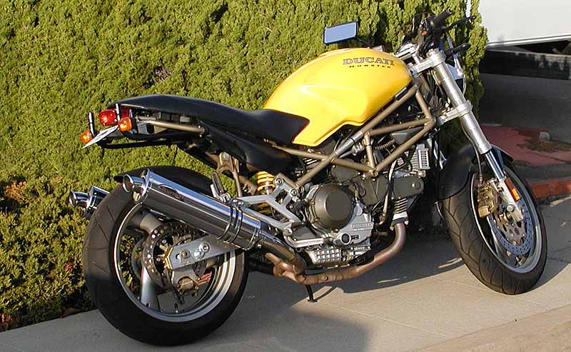
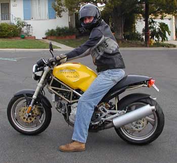 Sitting on Pongo! sure made me smile!!
I think this picture was on my very first voyage with Pongo.
We had some issues to sort out since then... mostly fuel problems.
His fuel pump was shot, and he protested by leaving me stranded some 120 miles from home.
Thankfully, it was 120 miles away right off o I-8 in El Centro ... AFTER some 200 miles of back country riding!
With a new vacuum operated fuel pump, we've ridden again, but that oil leak isn't completely gone and Zina says Pongo smells bad.
Oh, and he smokes bad, too.
Soooo, sometime soon, a pair of FbF hi comp pistons are going to find their way into Pongo!
He'll get a thorough rework in his heads, too... new bearings, guides, seals, and a valve/seat regrind, too.
Sitting on Pongo! sure made me smile!!
I think this picture was on my very first voyage with Pongo.
We had some issues to sort out since then... mostly fuel problems.
His fuel pump was shot, and he protested by leaving me stranded some 120 miles from home.
Thankfully, it was 120 miles away right off o I-8 in El Centro ... AFTER some 200 miles of back country riding!
With a new vacuum operated fuel pump, we've ridden again, but that oil leak isn't completely gone and Zina says Pongo smells bad.
Oh, and he smokes bad, too.
Soooo, sometime soon, a pair of FbF hi comp pistons are going to find their way into Pongo!
He'll get a thorough rework in his heads, too... new bearings, guides, seals, and a valve/seat regrind, too.
|
 (6.2003)
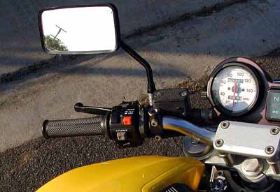
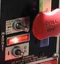
Before the trip to Laguna world superbikes races in 2003, I fitted an aftermarket switch group.
I saw this in one of my vendor's catalogs and thought I'd fit it and try it out before offering it for sale to my customers.
I like being able to turn off the headlight, as Pongo's battery isn't very new and the starter acts tired.
I've got a full on switch webpage talking about doing the switch.
(6.2003)
Before the trip to Laguna world superbikes races in 2003, I fitted an aftermarket switch group.
I saw this in one of my vendor's catalogs and thought I'd fit it and try it out before offering it for sale to my customers.
I like being able to turn off the headlight, as Pongo's battery isn't very new and the starter acts tired.
I've got a full on switch webpage talking about doing the switch.
|
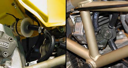
 (8.3.2003) At the same time, I also installed the Ventura Pack system.
If you've got a Monster with a "chopped tail", you will definitely not be able to use the proper "carbureted Monster" L-Bracket set.
Instead, you can get the kit for the 2000 M900ie.
Once I had the wrong kit, I realized that I would be able to make the same set from Zina's bike work on mine.
I added some "KTM sytle" turn signals as they have the same appearance as OEM but mount in a more traditional wire through bolt manner.
The previous "winkers" were all but useless in the daylight.
The mods worked out well and the Ventura pack happily hauled all my trash to and from Laguna well.
Pongo also did well other than the continuous spewing forth of burned oil from the mufflers.
I've got my 11.2:1 compression JE pistons in hand and just worked out a deal to purchase some 900SS heads, so a top end rebuild should be forthwith.
(yeah right!)
(8.3.2003) At the same time, I also installed the Ventura Pack system.
If you've got a Monster with a "chopped tail", you will definitely not be able to use the proper "carbureted Monster" L-Bracket set.
Instead, you can get the kit for the 2000 M900ie.
Once I had the wrong kit, I realized that I would be able to make the same set from Zina's bike work on mine.
I added some "KTM sytle" turn signals as they have the same appearance as OEM but mount in a more traditional wire through bolt manner.
The previous "winkers" were all but useless in the daylight.
The mods worked out well and the Ventura pack happily hauled all my trash to and from Laguna well.
Pongo also did well other than the continuous spewing forth of burned oil from the mufflers.
I've got my 11.2:1 compression JE pistons in hand and just worked out a deal to purchase some 900SS heads, so a top end rebuild should be forthwith.
(yeah right!)
|
 (10.2003)
In October of 2003, I decided to do a top end rebuild on Pongo.
I wasn't sure what to expect but I found that the Nik-a-sil coating on the cylinders was badly worn.
Like at least .010", maybe more.
There was a recess in the area swept by the piston rings.
The space above and below the rings' swept area looked fine, with full cross hatching, while the swept area was smooth.
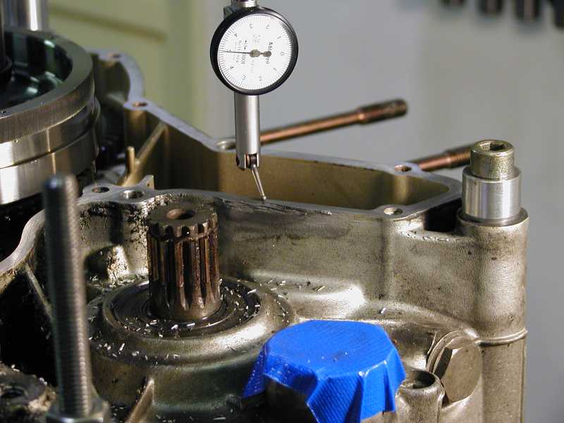
I also took the time to address the engine case where the chain had broken and damaged the cover for a previous owner.
You can see the test gauge in the picture.
I set the engine on some blocks and bolted it down to the milling machine.
There was .015" of depth where the gauge is positioned relative to the rest of the gasket surface.
This was simply too much gap for gasket sealer to manage.
I checked that the rest of the surface was even and it was within .001" for the rest of the gasket area of the alternator cover.
So I drove around the gasket surface with a 3/4" end mill cutting .015" deep.
Normally, this reduction in height could cause an issue, but I commissioned a gasket maker to make alternator cover gaskets.
They're 1/64 of an inch thick, so it will almost make that gap up.
(10.2003)
In October of 2003, I decided to do a top end rebuild on Pongo.
I wasn't sure what to expect but I found that the Nik-a-sil coating on the cylinders was badly worn.
Like at least .010", maybe more.
There was a recess in the area swept by the piston rings.
The space above and below the rings' swept area looked fine, with full cross hatching, while the swept area was smooth.
I also took the time to address the engine case where the chain had broken and damaged the cover for a previous owner.
You can see the test gauge in the picture.
I set the engine on some blocks and bolted it down to the milling machine.
There was .015" of depth where the gauge is positioned relative to the rest of the gasket surface.
This was simply too much gap for gasket sealer to manage.
I checked that the rest of the surface was even and it was within .001" for the rest of the gasket area of the alternator cover.
So I drove around the gasket surface with a 3/4" end mill cutting .015" deep.
Normally, this reduction in height could cause an issue, but I commissioned a gasket maker to make alternator cover gaskets.
They're 1/64 of an inch thick, so it will almost make that gap up.
|
 (11.2003) Next, I decided to pull the studs.
I could / should have left them be, but more than one of them were pretty rusty, so I got stupid and decided to pull the studs.
Part of the reason for wanting to change them was that I had a shipment of studs coming from APE, American Performance Engineering.
Anyway, one of the studs absolutely froze.
After twisting it (Yes, twist!), I cut it off to get purchase closer to the engine case with my stud puller.
Then it snapped just off the case.
OK, so I get more purchase... only to have it break below the case.
Click the picture to the right to read about how I performed the repair of the broken cylinder stud!
(11.2003) Next, I decided to pull the studs.
I could / should have left them be, but more than one of them were pretty rusty, so I got stupid and decided to pull the studs.
Part of the reason for wanting to change them was that I had a shipment of studs coming from APE, American Performance Engineering.
Anyway, one of the studs absolutely froze.
After twisting it (Yes, twist!), I cut it off to get purchase closer to the engine case with my stud puller.
Then it snapped just off the case.
OK, so I get more purchase... only to have it break below the case.
Click the picture to the right to read about how I performed the repair of the broken cylinder stud!
|
 (12.2003)
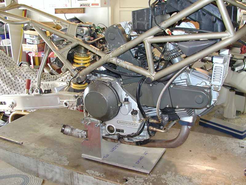
In November, I saw advertisement of parted out crashed Monster 900.
I made an offer for "the Carcass" and it was accpeted.
We retrieved the Carcass while visiting family in the San Francisco area over Christmas.
The Carcass consisted of: 1997 M900 engine, bent frame, swingarm (+ rear suspension), rear wheel, smashed tank, airbox.
(12.2003)
In November, I saw advertisement of parted out crashed Monster 900.
I made an offer for "the Carcass" and it was accpeted.
We retrieved the Carcass while visiting family in the San Francisco area over Christmas.
The Carcass consisted of: 1997 M900 engine, bent frame, swingarm (+ rear suspension), rear wheel, smashed tank, airbox.
(1.2004) I fabbed up the engine stand which enabled me to really get to work. "Pongo" went from what you see here to what you see in the next frame in only a day. |
 (1.31.2004)
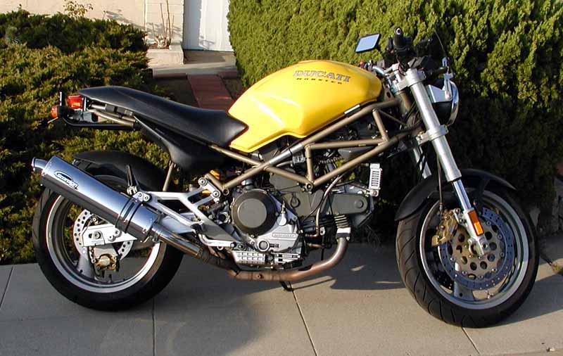
Yaay! I got to ride Pongo again!
I'm excited about a few things.
One: The Scorpion pipes sound killer!
Way deep and rumbly, but Zina says not too loud.
Two: The 19,000 mile donor motor from The Carcass works great!
Zina really digs how the engine doesn't burn a ton of oil and isn't all stinky.
I like that Pongo again has power.
Almost real power.
While goofing about in town, I was able to hoist the front wheel under power in first gear.
And this is with the 750 heads!!
(1.31.2004)
Yaay! I got to ride Pongo again!
I'm excited about a few things.
One: The Scorpion pipes sound killer!
Way deep and rumbly, but Zina says not too loud.
Two: The 19,000 mile donor motor from The Carcass works great!
Zina really digs how the engine doesn't burn a ton of oil and isn't all stinky.
I like that Pongo again has power.
Almost real power.
While goofing about in town, I was able to hoist the front wheel under power in first gear.
And this is with the 750 heads!!
|
 (1.31.2004)
What next?
I've got plans for 3 more steps with Pongo.
1) To install dyna coils kit and then get baseline dyno run.
2) Then install the mbp ducati testarosso heads and FCR41s on short intake manifolds and get another dyno run.
Here, we look for impressive numbers.
3) Now, transfer the Testarosso heads to Pongo's original engine with the 966 kit in it and also degree in the cams.
This is the step where we're shooting for numbers previously unseen on the dyno for 2V engine.
(1.31.2004)
What next?
I've got plans for 3 more steps with Pongo.
1) To install dyna coils kit and then get baseline dyno run.
2) Then install the mbp ducati testarosso heads and FCR41s on short intake manifolds and get another dyno run.
Here, we look for impressive numbers.
3) Now, transfer the Testarosso heads to Pongo's original engine with the 966 kit in it and also degree in the cams.
This is the step where we're shooting for numbers previously unseen on the dyno for 2V engine.
|