| It's all Guy's fault. I should have been happy with my Pongo the way he is. Are we ever happy enough to leave things be? Well, no. I had Pongo's engine out for new cylinders and to repair a broken cylinder head stud and also had a spare engine in Pongo, so he wasn't out of commission. Thus I was unusually susceptible to Guy's convincing to send him my heads for his Testarosso head work. To reach Guy Martin (pronounced Geee and not Jeeee) go to mbpducati.ca. His process gets 90+ hp out of a 904 engine by changing the parts from the heads up. Yes, that's with the stock 9.2:1 pistons! |
Guy took my "small valve" M900 and converted the hemispherical combustion chamber to the "bathtub" style chamber on proper 900 heads.
Then he machined out the heads to put in HUGE valves and special valve seats.
The exhaust seat is beryllium copper or something crazy like that.
Next up, he fits his custom designed and purpose manufactured valves and starts his porting in conjunction with careful checks on the flowbench.
By applying engineering process to his work, Guy gets repeatable results.
In the chart, it is apparent that the real problem with Ducati 904 2V heads is getting air into the engine. The "stock" values in the above chart are for proper 900 "V2/V2" stamped heads and not the "W1/W2" 750 heads that are on my M900. With my heads, I supplied to Guy some ST2 cams that make .460" of lift. Alex Ortner brings more clarity the above graph: The two valve heads have terrible intake ports. The flow chart on the ports shows that there is a limit to the amount of air that will pass through the port. If you run a 9mm lift cam you get X amount of air if you run an 11mm lift cam you get virtually no increase in air flow. This flow limit absolutely limits the horsepower that these motors are capable of. It really doesn't mater what pistons, what valves, what carbs, what manifolds or whatever else is done if the ports aren't done properly, they won't flow more air. MBP heads show a 25% increase in air flow at .300" lift and a 50% increase at .500" lift. These numbers indicate that these heads will flow more air as the engine is able to use it. |
 After deburring the new 95mm (966cc) pistons and prepping the cylinders with new freeze plugs and blowing out the "dust", I used 1/4-28 tap down in the oil passages in the top of the cylinders.
You'll note there is layer of aluminum, then an open passageway, and then the "well" where they continued drilling.
Grease up the tap, run it down through the first "layer" of aluminum, and then thread in 1/4-28 x 1/2" set screw to block the oil port.
Then set the ring gap and set the pistons in the bores using WD40 as assembly lube.
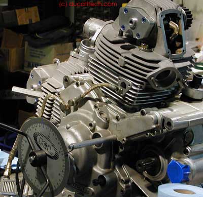
The first "real" step with the heads is once the engine is somewhat assembled, you set up the degree wheel.
As you see, I thread a stud into 1/2" aluminum round bar and hang off the engine.
At the other end is the pointer, a short section of hanger wire.
I could use something more accurate, but I have found that the repeatability of accuracy when turning the engine is at about 1 degree of resolution given the system.
After deburring the new 95mm (966cc) pistons and prepping the cylinders with new freeze plugs and blowing out the "dust", I used 1/4-28 tap down in the oil passages in the top of the cylinders.
You'll note there is layer of aluminum, then an open passageway, and then the "well" where they continued drilling.
Grease up the tap, run it down through the first "layer" of aluminum, and then thread in 1/4-28 x 1/2" set screw to block the oil port.
Then set the ring gap and set the pistons in the bores using WD40 as assembly lube.
The first "real" step with the heads is once the engine is somewhat assembled, you set up the degree wheel.
As you see, I thread a stud into 1/2" aluminum round bar and hang off the engine.
At the other end is the pointer, a short section of hanger wire.
I could use something more accurate, but I have found that the repeatability of accuracy when turning the engine is at about 1 degree of resolution given the system.
|
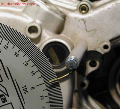
 Step 2 is to figure out where zero really is.
The pic above was actually taken AFTER I had zeroed in the degree wheel.
I happen to know that in a 2V engine, my piston stop (shown here threaded into forward cylinder) takes up about 60 degrees of rotation.
So I put the degree wheel "near zero", then turn the engine to 60 degrees away from TDC, thread in the stop, slowly turn the engine stops and note the angle (example, 34).
Then I thread out the stop, go to 40 or 50 past TDC, insert the stop, and rotate backwards (against the starter motor) until the engine stops and again note the angle (example, 26).
Now, with the crank against this stop, make the degree wheel point to 30 and you REALLY know where TDC is.
Step 2 is to figure out where zero really is.
The pic above was actually taken AFTER I had zeroed in the degree wheel.
I happen to know that in a 2V engine, my piston stop (shown here threaded into forward cylinder) takes up about 60 degrees of rotation.
So I put the degree wheel "near zero", then turn the engine to 60 degrees away from TDC, thread in the stop, slowly turn the engine stops and note the angle (example, 34).
Then I thread out the stop, go to 40 or 50 past TDC, insert the stop, and rotate backwards (against the starter motor) until the engine stops and again note the angle (example, 26).
Now, with the crank against this stop, make the degree wheel point to 30 and you REALLY know where TDC is.
|
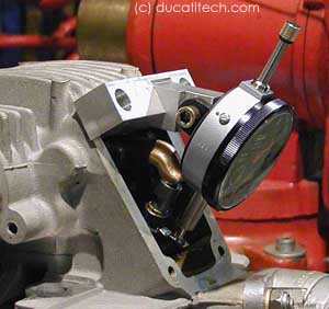 Now, fix your dial indicator and ensure the valve is closed (TDC) and set the degree wheel's zero.
Here, Guy gave me specific information as part of his "recipe".
Actually, some may note a change on this info from earlier.
We talked again and we clarified the routine.
Put a feeler gauge in between the opening shim and rocker arm to take up the slack caused by shim clearance.
Turn the engine, note the angle when there is .040" of lift on the intake valve - this will determine the degree values of opening and closing.
We talked about the lift numbers and you can use either .030" or .040" - it doesn't really matter as we are computing theoretical lobe center.
Now, fix your dial indicator and ensure the valve is closed (TDC) and set the degree wheel's zero.
Here, Guy gave me specific information as part of his "recipe".
Actually, some may note a change on this info from earlier.
We talked again and we clarified the routine.
Put a feeler gauge in between the opening shim and rocker arm to take up the slack caused by shim clearance.
Turn the engine, note the angle when there is .040" of lift on the intake valve - this will determine the degree values of opening and closing.
We talked about the lift numbers and you can use either .030" or .040" - it doesn't really matter as we are computing theoretical lobe center.
The desired location for top end power is 105~107° lobe centers. These numbers below were taken after I checked squish (talked about below). This is the first step of the circular process and the numbers here are from the final step. On the F cylinder, I got opens at 31° BTDC and closes at 70.5° ABDC. Now, Guy gives me cookbook recipe to find lobe center (assuming concentricity)... With STM pulley at "CW+1" position, or advanced 2 degrees: 31 + 180 + 70.5 = 281.5 281.5 / 2 = 140.75 140.75 - 31 = 109.75Note that in the above areas, the underlined portions could be done via a spreadsheet or calculator. In fact, you can do something of short hand notation. I actually made an Excel spreadsheet so I could take notes on a laptop computer while measuring the values. Here are notes from the vertical cylinder: STM @ +6 CW: 29 + 180 + 70 = 279 / 2 = 139.5 - 29 = 110.5 STM @ +7 CW: 30.5 + 180 + 68 = 278.5 / 2 = 139.25 - 30.55 = 108.75What you'll notice is that the two cylinders' cams differ by some 12 degrees. There is a lot of opportunity for slop in the system besides manufacturing tolerance... There are 2 pulleys for each cylinder, each with their own woodruff keys, which allow for shifting. Also, when installing a new pulley nut, I've found that this can retard the cams by 2 degrees as compared to using an old nut to torque the pulley. When switching from a "tired" used pulley nut to a fresh one, there is noticeable difference in tightening force. Not torquing the nuts is another 2° difference, so you can't try to cheat and save time that way! Another observation to be made is how the vertical cylinder is "only" able to be advanced to 109°. This limits the front cylinder to 109° instead of the more optimal 105° to 107° that we would otherwise adjust to. Also, when rotating the engine, only turn the engine forward. I have observed 2°~4° variation if you go past your lift mark and then rotate the engine backwards and then go forward again to find the mark. I believe this to be due to the gear lash between timing layshaft gear and the crank drive gear. With no belts installed, I noticed that the timing shaft could shift back and forth noticeably. When taking measurements, I would take a series of 3 or 4 open+close lift values to ensure the numbers are good. This is where the laptop computer and the Excel spreadsheet with a little math helps a LOT. Doing lots of measurements and getting a feel for the process also helps your confidence when reading the values. Better accuracy can be had with a larger diameter degree wheel. For this build, I am using the same K&L degree wheel that I sell. I think it is at the lower limit for size... just large enough to get the job done. |
 Now we do something important.
Yeah, yeah all that stuff above is important, but that's for power.
This is important.
Time to check squish for the "squish band" and "valve to piston clearance".
This is normally called "claying the head" or some such.
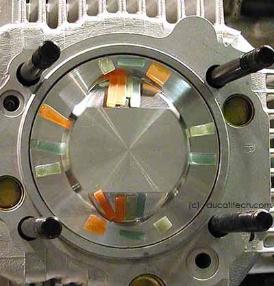
We'll use wax.
There are 4 thicknesses of the wax: .040", .050", .065", and .075".
Their colors are dark green, light green, orange, and burnt orange.
Due to the closeness of the colors, I keep the wax sticks on top of their respective baggies and you'll notice that I applied them in repeating similar pattern.
Before applying the wax to the pistons, I wiped the pistons off with a rag and contact cleaner (or "brake cleaner").
Then I spray WD40 on rag and wipe the combustion chamber.
Now assemble engine and belts and s-l-o-w-l-y turn it over.
On the forward / horizontal cylinder, I heard the .065" wax lift off the piston and stick to the head...
Now we do something important.
Yeah, yeah all that stuff above is important, but that's for power.
This is important.
Time to check squish for the "squish band" and "valve to piston clearance".
This is normally called "claying the head" or some such.
We'll use wax.
There are 4 thicknesses of the wax: .040", .050", .065", and .075".
Their colors are dark green, light green, orange, and burnt orange.
Due to the closeness of the colors, I keep the wax sticks on top of their respective baggies and you'll notice that I applied them in repeating similar pattern.
Before applying the wax to the pistons, I wiped the pistons off with a rag and contact cleaner (or "brake cleaner").
Then I spray WD40 on rag and wipe the combustion chamber.
Now assemble engine and belts and s-l-o-w-l-y turn it over.
On the forward / horizontal cylinder, I heard the .065" wax lift off the piston and stick to the head...
|
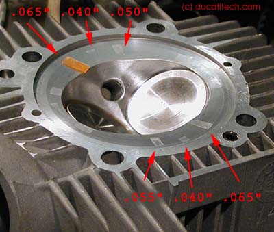 Stop turning the engine when it's away from TDC and take off the cylinder head.
You'll notice the change in light reflection where the wax touched the surface of the head.
Our goal for the squish band is not under .040" and not over .050".
If this was a customer engine, it would get the next larger base gasket (0.6mm vice 0.4mm) but this is my engine...
And the plan is that it will not stay assembled in this configuration very long.
Stop turning the engine when it's away from TDC and take off the cylinder head.
You'll notice the change in light reflection where the wax touched the surface of the head.
Our goal for the squish band is not under .040" and not over .050".
If this was a customer engine, it would get the next larger base gasket (0.6mm vice 0.4mm) but this is my engine...
And the plan is that it will not stay assembled in this configuration very long.
Also, we want to make sure that the valves are at least .060" away from the relief pockets. On the rear / vertical cylinder, there were no impressions whatsoever of the valves on the reliefs. Also, the .040" wax did not hit the head at all. On the forward / horizontal cylinder, the .075" wax barely got impression from the intake valve. Good to go. To reiterate why the process involves degreeing cams, checking squish, and then degreeing cams again is because you want the cams near to final time when checking squish. Part of squish is to make sure the valves don't get too close to the pistons as well as that the pistons don't get too close to the heads. |
 I carefully wipe the wax off the piston using dental pick.
Note that the wax has a sticky backing on it.
It's best to "wipe" from the inboard corner, away from critical squish area.
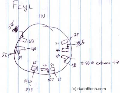
To figure out actual squish, we measure the wax chunks with digital calipers.
This clearance gauge wax is particularly robust and easily measured with the flat surfaces of calipers.
You see the notes.
While .040" is what is recommended, .035" would be a racer's limit.
My .0375"~.038" values are pushing conservative, but this build is proof of concept.
I carefully wipe the wax off the piston using dental pick.
Note that the wax has a sticky backing on it.
It's best to "wipe" from the inboard corner, away from critical squish area.
To figure out actual squish, we measure the wax chunks with digital calipers.
This clearance gauge wax is particularly robust and easily measured with the flat surfaces of calipers.
You see the notes.
While .040" is what is recommended, .035" would be a racer's limit.
My .0375"~.038" values are pushing conservative, but this build is proof of concept.
You will see the notes about .036" and .037" ... those measurements were taken at the extreme edges of the wax. I can't consider them completely reliable. Ultimately, I ended up using a 0.35 mm base gasket on the rear cylinder and double checking its squish. Now both cylinders are at .037" squish. This is just below "safe street" recommendation of .040" of squish. Since I will soon swap out these heads to a 904cc engine with stock pistons, I'm not quite as worried about the .040" safer value. Also, since this engine will not see ultra high rev racing use, I'm comfortable with the slightly aggressive numbers. Now remove the wax and residue, pull up the cylinders (with pistons inside only having one circlip), coat the base gasket, install wrist pins and clips and torque the heads down according to the manual. Oh and how installing those pin clips annoyed me! The forward cylinder's clip kept leaping off and falling in the crankcase (where I could easily retrieve with magnet). For rear / vertical cylinder, I carefully laid out rags. Of course, since I took the precaution, the clip went in on the first try.
Note: |
 How / where to get all this?
(or beware of sales pitch!) mbpducati.ca and ca-cycleworks.com are partnering together to bring this package and recipe to customers. You can contact either about arranging for the work. ca-cycleworks.com has special arrangement to ship parts to mbpducati.ca regardless of "who gets paid", so please take advantage of this for your easiest convenience. UPS Ground to addresses in the US will be less costly than FedEx International and also without hassle of pro forma invoices and HSTA codes. As part of this collaboration, ca-cycleworks.com is maintaining inventory of FCR 41 singles kits (jetted and set up to Guy Martin's specifications), special designed oil lines and fittings, and set screws for the cylinders. ca-cycleworks.com is also arranging the manufacture of short intake manifolds to ensure reliable supply.
|